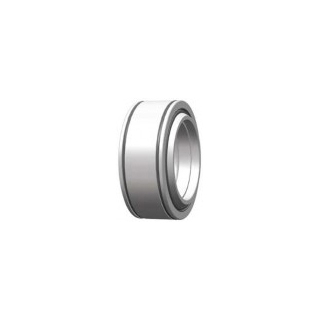
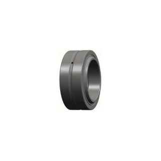
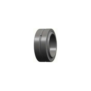
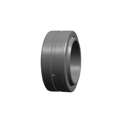
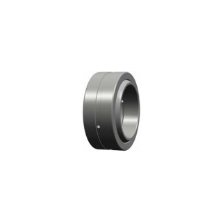
GEH Steel / Copper Alloy Series
GEH Steel / Copper Alloy Series Radial Spherical Plain Bearing dimensions and technical data
İnceleLoad rating
Dynamic rating is used for calculations when the spherical plain bearing is subjected to dynamic stress. It represents the load, constant in magnitude and direction, under which a basic rating service life, expressed as a sliding distance, will be attained for continuous oscillating movement at a defined sliding velocity and at room temperature. It presupposes that the load acting on radial and angular spherical plain bearings and on rod ends is purely radial and that the load acting on spherical plain thrust bearings is purely axial and acts centrically. Dynamic stresses occur when tilting, oscillatory or rotational movements are made under load as well as microsliding movements under alternating loads, e.g resulting from vibration, or loads which alternate at high frequency. The various types of dynamic stress often occur in combination. The values of load ratings are always dependent on the definition used. It is therefore not always possible to make direct comparisons with load ratings published by other manufactures.
The static load rating is used when spherical plain bearings stand still under load(or make occasional alignment movements) and it should also be considered when dynamically loaded bearings are subjected to heavy shock loads. The static load rating represents the load which can be taken up by a spherical plain bearing when static contact stress of bearing contact surface reaches the material stress limit. It is valid at room temperature and it is presupposed that the surrounding components prevent deformation of the bearing. At higher temperature, the static load rating must be multiplied by a temperature factor, depend on the sliding contact surface combination. The temperature factor are the same as for dynamically stressed bearing. It is also necessary to take into consideration the permissible temperature range for the various sliding contact surface combinations. For rod ends, it is the strength of the rod end housing under stationary load which is considered. The rod end static load ratings give a safety factor of 1.2 times the tensile strength of the rod end housing material.
Service life
The service life of a spherical plain bearing operated under mixed or dry friction conditions is determined by the increase in bearing clearance or bearing friction caused by progressive wear of the sliding surfaces, plastic deformation of the sliding material or fatigue of the sliding surface. Depending on the application, the permissible wear or permissible increase in friction will be different. This means that under the same operating conditions the service life which can be obtained in practice will be different.
The service life of a spherical plain bearing is the number of oscillating movements, or the number of operating hours, which the bearing will service before a defined increase in bearing clearance or a defined increase in friction is reached.
The effective service life is that life which will be attained by a given spherical plain bearing under actual operating conditions. It is determined by the magnitude and type of load, but also by several other factors, such as contamination, corrosion, high-frequency load and movement cycles, shock etc. Some of these factors are impossible to determine or can only be determined with difficulty.
Bearing contact pressure
If an adequate operating life is to be achieved, a basic requirement is that the bearing contact pressure is compatible with the operating conditions. The bearing contact pressure identifies the surface pressure occurring in the bearing and is a decisive criterion for the assessment of a spherical plain bearing in each individual application.
| p=k.P/Cd | |
| p: contact pressure | N/mm2 |
| k: contact pressure parameter | N/mm2 |
| Cd: dynamic load rating | kN |
| P: equivalent dynamic bearing load | kN |
| Contact surface combination | Value of load ratio Cd/P |
| Steel/steel | 2 |
| Steel/bronze | 2 |
| Steel/PTFE fabric | 1.75 |
| Steel/PTFE composite material | 2 |
| Steel/copper alloy | 2 |
| Contact surface combination | Load factor k |
| Steel/steel | 100 |
| Steel/bronze | 50 |
| Steel/PTFE fabric | 100 |
| Steel/PTFE composite material | 100 |
| Steel/copper alloy | 100 |
Bearing internal clearance
Bearing internal clearance is defined as the total distance through which one ring can be moved radially (radial internal clearance) or axially (axial internal clearance) in relation to the other ring under a defined measuring load.
It is necessary to distinguish between the internal clearance of a bearing before it is mounted and the internal clearance of a mounted bearing when in operation (operational clearance).The initial clearance will always be greater than the operational clearance because the rings are expanded or compressed by interferences fits and as a result of the differences in thermal expansion of the bearing rings and mating components.
The bearing internal clearance referred to as basic has been selected so that when bearings are mounted generally recommended and operate under normal conditions a suitable operational clearance will be obtained. For other conditions, e.g. where both rings are mounted with an interference fit or where unusual temperatures prevail, bearings with greater or smaller internal clearance than normal may be required.
Lubrication
For spherical plain bearings requiring maintenance which are of the steel-on-steel type, the purpose of the lubrication is primarily to reduce wear, reduce friction and prevent scuffing. Also the grease serves to protect the bearings against corrosion.The frequency of relubrication of the bearing during its operation will appreciably extend the service life.
For steel-on-PTFE fabric spherical plain bearings, there is a transfer of PTFE from fabric to the opposing steel surface of the inner ring. Any lubrication of the sliding contact surfaces would disturb this transfer and shorten bearing life. Therefore, lubrication of these bearings is not advisable.
For steel-on-PTFE composite material spherical plain bearings, as a ruleit must not be lubricated. When operating conditions are such that enhanced sealing and protection against corrosion are required, it is recommended that the bearing or the space surrounding the bearing is filled with lithium base grease.
MoS 2: The wear occurring during running-in phase proceeds all the more favourably the more MoS 2 is embedded in the porous-crystalline manganese phosphate. There are two type: wet MoS 2 and dry MoS 2. Wet MoS 2 is treated with dip coating, dry MoS 2 is treated with spray coating. The effect of dry MoS 2 is superior to wet MoS 2. If customer need dry MoS 2, please consult marketing department.
Sealing
Most bearing arrangements must be sealed to prevent external contamination and damp from entering the bearing. The efficiency of the sealing has a decisive influence of the service life of the bearing. LS seal has two type, see table 1.
Table 1
| Seal | Illustration | Design characteristics | Suitability |
| 2RS Design | Polyurethane (-30℃ ∽ +130℃) | 1. For compact bearing arrangement, mainly indoors. | |
| 2. For cramped spaces | |||
| Nylon (-30℃ ∽ +130℃) | 3. For high sealing demands when combined with and outboard seal | ||
| 4. For bearings which are to rotate | |||
| 5. For long service life with minimum maintenance | |||
| 2GS Design | Rubbing seal of elastomer with steel backing (-25℃ ∽ +120℃) | 1. For compact bearing arrangement,mainly indoors | |
| 2. For high sealing demands | |||
| 3. For bearings which are to rotate | |||
| 4. For long service life with minimum maintenance | |||
| 5. For difficult operating conditions in the presence of sand or mud |
Accuracy
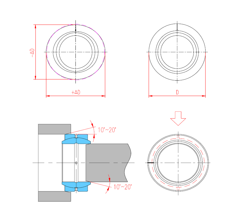
The tolerances apply to outer ring without surface treatment and splitting.
The outer rings become slightly out of round due to splitting. The roundness of the outer ring is restored once it is fitted in a housing bore produced in accordance with the specifications (Figure1).
Measurements taken of the outside diameter of the unfitted bearing cannot be used as the original actual values for the outside diameter.
Figure1
Fitting
To facilitate mounting, the ends of pins or shafts and the edges of housing bores should have a lead chamfer of 10° to 20°. The bearings can be more easily pushed into position and there is little risk of damage to the mating surfaces being caused by skewing of the bearing (Figure 2).
In radial spherical plain bearings with split outer rings, the joints are offset at 90 ℃ from the main load direction. The lubrication holes of bearings requiring maintenance are thus positioned in the load zone. This allows good lubricant distribution in the load zone area (Figure 3).
Figure 2 Figure 3
Rules and guidelines
1.The assembly area must be kept clean and free from dust.
2.The bearings must be protected from.
3.The bearings must always be located concentrically.
Mechanical and thermal assistance
1.Direct blows using a hammer and drift on the end faces of thbearing rings must be avoided.
2.Fitting forces must always be applied to the inner ring.If these forces are directed through the sliding surfaces,the bearings may jam during fitting (Figure 4).
3.If bearings are fitted on the shaft and in a housing at the same time,fitting tools must be used which act simultaneously on the end faces of the inner and outer ring (Figure 5).
4.Larger bearings must be using special fitting equipment (Figure 6).
Thermal assistance
When bearing is difficultly mounted,bearing heating and bearing housing heating can be done before mounting, but took notice that:
1.Spherical plain bearings must not be heated above +130 ,higher temperatures damage the seals.
2.Spherical plain bearings must not be heated in an oil bath, unless:
a.This impairs the triological system of maintenance-free bearings.
b.It changes the molybdenum disulphide concentration on the surfaces in bearing with a steel/steel sliding contact surface.
3.Bearings must not be heated using a naked flame,unless:
a.The material undergoes excessive localized heating and its hardness is reduced. Futhermore, stresses are induced in the bearing.
b.The seals could melt.
c.Maintenance-free sliding surfaces could be damaged.
Fitting by refrigeration
The cooling also can be used for bearing mounting, but took notice that.
The inner rings of spherical plain bearings with a steel/steel sliding contact surface undergo structural change at temperatures below -61℃.
Adhesive bonding of bearing rings
If the recommended fits are adhered to, it is not necessary to use adhesive on the bearing rings. In order to make it easy, the bearing is mounted with a loose fit, then the adhesive bonding is considered to be used for bonding shaft and inner ring,or bonding bearing housing snd outer ring, but took notice that, adhesives may only be used on spherical plain bearings with steel/steel sliding contact surfaces under the following conditions:
1.The surfaces to be bonded must be clean and free from grease.
2.It must be insuranced that the lubricant ducts and lubricant holes are not blocked by adhesive.
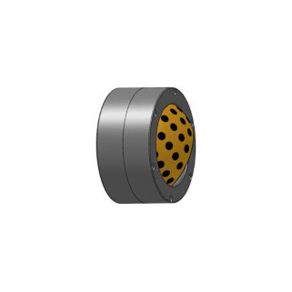
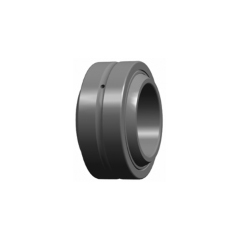
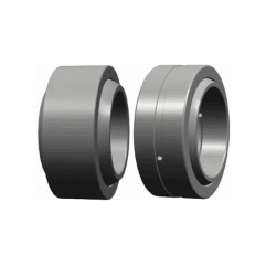
Radial spherical plain bearings have an inner ring with a sphered convex outside surface and an outer ring with a correspondingly sphered but concave inside surface. Their design makes them particularly suitable for bearing arrangements where alignment movements between shaft and housing have to be accommodated, or where oscillating or recurrent tilting or slewing movements must be permitted at relatively slow sliding speeds. LS radial spherical plain bearings are available with different sliding contact surface combinations, i.e. the sliding surfaces of inner and outer rings are made from different materials. There are two main groups: spherical plain bearings requiring maintenance (steel-on-steel) and maintenance-free spherical plain bearings.
LS radial spherical plain bearings requiring maintenance(steel-on-steel) generally have hardened sliding contact surface on both rings. The surfaces are treated with molybdenum disulphide and phosphated. It has characteristics of wear-resistance and wear-corrosion. Bearings with this sliding contact surface combination require regular relubrication. The high strength of the sliding contact surfaces makes these bearings especially suitable for bearing arrangements where heavy loads of alternating direction, shock loads or heavy static loads have to be accommodated.
LS maintenance-free spherical plain bearings sliding contact surfaces have four groups: steel-on-PTFE composite material, steel-on-PTFE fabric, steel-on-copper alloy and steel-on-PTFE plastic. Dynamic load support capability of steel-on-PTFE fabric spherical plain bearings is higher than that of steel-on-PTFE composite material. They have very low friction and can be operated without maintenance. They are used for applications where long bearing lives are required without maintenance, or where operating conditions, such as inadequate lubrication or the absence of lubrication make the use of steel-on-steel bearing inadvisable.
Tolerances for radial spherical plain bearings
Tolerances for radial spherical plain bearings(except for series GEBK…S,GEBJ…S,GEBJ…C,GEFZ…S,GEFZ…C,GEFZ…T,GEK…XS-2RS)
| Inner ring | |||||||||||||
| d mm | ∆dmp | ∆dmp* | Vdp | Vdmp | Vdp* | Vdmp* | ∆Bs | ∆Bs* um | |||||
| over | incl. | max. | min. | max. | min. | max. | max. | max. | max. | max. | min. | max. | min. |
| - | 18 | 0 | -8 | +18 | 0 | 8 | 6 | 18 | 14 | 0 | -120 | 0 | -180 |
| 18 | 30 | 0 | -10 | +21 | 0 | 10 | 8 | 21 | 16 | 0 | -120 | 0 | -210 |
| 30 | 50 | 0 | -12 | +25 | 0 | 12 | 9 | 25 | 19 | 0 | -120 | 0 | -250 |
| 50 | 80 | 0 | -15 | +30 | 0 | 15 | 11 | 30 | 22 | 0 | -150 | 0 | -300 |
| 80 | 120 | 0 | -20 | +35 | 0 | 20 | 15 | 35 | 26 | 0 | -200 | 0 | -350 |
| 120 | 180 | 0 | -25 | +40 | 0 | 25 | 19 | 40 | 30 | 0 | -250 | 0 | -400 |
| 180 | 250 | 0 | -30 | +46 | 0 | 30 | 23 | 46 | 35 | 0 | -300 | 0 | -460 |
| 250 | 315 | 0 | -35 | +52 | 0 | 35 | 26 | 52 | 39 | 0 | -350 | 0 | -520 |
| 315 | 400 | 0 | -40 | +57 | 0 | 40 | 30 | 57 | 43 | 0 | -400 | 0 | -570 |
| 400 | 500 | 0 | -45 | - | - | 45 | 34 | - | - | 0 | -450 | - | - |
| 500 | 630 | 0 | -50 | - | - | 50 | 38 | - | - | 0 | -500 | - | - |
| 630 | 800 | 0 | -75 | - | - | 75 | 56 | - | - | 0 | -750 | - | - |
The deviations in the columns with symbol * apply to spherical plain bearings of series GEEW…ES.
| Outer ring | |||||||
| D mm | ∆Dmp um | VDp um | VDmp um | ∆Cs um | |||
| Over | incl. | max. | min. | max. | max. | max. | min. |
| - | 18 | 0 | -8 | 10 | 6 | 0 | -240 |
| 18 | 30 | 0 | -9 | 12 | 7 | 0 | -240 |
| 30 | 50 | 0 | -11 | 15 | 8 | 0 | -240 |
| 50 | 80 | 0 | -13 | 17 | 10 | 0 | -300 |
| 80 | 120 | 0 | -15 | 20 | 11 | 0 | -400 |
| 120 | 150 | 0 | -18 | 24 | 14 | 0 | -500 |
| 150 | 180 | 0 | -25 | 33 | 19 | 0 | -500 |
| 180 | 250 | 0 | -30 | 40 | 23 | 0 | -600 |
| 250 | 315 | 0 | -35 | 47 | 26 | 0 | -700 |
| 315 | 400 | 0 | -40 | 53 | 30 | 0 | -800 |
| 400 | 500 | 0 | -45 | 60 | 34 | 0 | -900 |
| 500 | 630 | 0 | -50 | 67 | 38 | 0 | -1000 |
| 630 | 800 | 0 | -75 | 100 | 56 | 0 | -1100 |
| 800 | 1000 | 0 | -100 | 135 | 75 | 0 | -1200 |
| 1000 | 1250 | 0 | -125 | 190 | 125 | 0 | -1300 |
Tolerances for series GEBK…S
| Inner ring | |||||
| d mm | ∆dmp um | ∆Bs um | |||
| over | incl. | max. | min. | max. | min. |
| - | 6 | +12 | 0 | 0 | -100 |
| 6 | 10 | +15 | 0 | 0 | -100 |
| 10 | 18 | +18 | 0 | 0 | -100 |
| 18 | 30 | +21 | 0 | 0 | -100 |
| Outer ring | |||||
| D mm | ∆Dmp um | ∆Cs um | |||
| over | incl. | max. | min. | max. | min. |
| 10 | 18 | 0 | -11 | +100 | -100 |
| 18 | 30 | 0 | -13 | +100 | -100 |
| 30 | 50 | 0 | -16 | +100 | -100 |
| 50 | 80 | 0 | -19 | +100 | -100 |
Tolerances for series GEBJ…S, GEBJ…C
| Inner ring | |||||
| d mm | ∆dmp um | ∆Bs um | |||
| over | incl. | max. | min. | max. | min. |
| - | 6 | +12 | 0 | 0 | -100 |
| 6 | 10 | +15 | 0 | 0 | -100 |
| 10 | 18 | +18 | 0 | 0 | -100 |
| 18 | 30 | +21 | 0 | 0 | -100 |
| Outer ring | |||||
| D mm | ∆Dmp um | ∆Cs um | |||
| over | incl. | max. | min. | max. | min. |
| 10 | 18 | 0 | -11 | 0 | -240 |
| 18 | 30 | 0 | -13 | 0 | -240 |
| 30 | 50 | 0 | -16 | 0 | -240 |
| 50 | 80 | 0 | -19 | 0 | -300 |
Tolerances for series GEFZ…S, GEFZ…C, GEFZ…T
| Inner ring | |||||
| d mm | ∆dmp um | ∆Bs um | |||
| over | incl. | max. | min. | max. | min. |
| - | 6 | +38 | -13 | +130 | -130 |
| 6 | 10 | +38 | -13 | +130 | -130 |
| 10 | 18 | +38 | -13 | +130 | -130 |
| 18 | 30 | +38 | -13 | +130 | -130 |
| Outer ring 6 | |||||
| D mm | ∆Dmp um | ∆Cs um | |||
| Over | incl. | max. | min. | max. | min. |
| 10 | 18 | 0 | -18 | +130 | -130 |
| 18 | 30 | 0 | -18 | +130 | -130 |
| 30 | 50 | 0 | -18 | +130 | -130 |
Tolerances for series GEK…XS-2RS
| Inner ring | |||||
| d mm | ∆dmp um | ∆Bs um | |||
| over | incl. | max. | min. | max. | min. |
| 18 | 30 | +33 | 0 | +50 | -110 |
| 30 | 50 | +39 | 0 | +50 | -110 |
| 50 | 60 | +46 | 0 | +50 | -140 |
| Outer ring | |||||
| D mm | ∆Dmp um | ∆Cs um | |||
| over | incl. | max. | min. | max. | min. |
| 50 | 80 | +30 | +11 | 0 | -130 |
| 80 | 120 | +35 | +13 | 0 | -130 |
| 120 | 150 | +40 | +15 | 0 | -130 |
The symbols of dimension and tolerance
d: Bearing bore diameter, nominal.
∆dmp: Single plane mean bore diameter deviation.
Vdp: Bore diameter variation in a single radial plane.
Vdmp: Mean bore diameter variation.
∆Bs: Deviation of a single width of the inner ring.
B: Width of inner ring, nominal.
D: Bearing outside diameter, nominal.
∆Dmp: Single plane mean outside diameter deviation.
VDp: Outside diameter variation in a single radial plane.
VDmp: Mean outside diameter variation.
∆Cs: Deviation of a single width of the outer ring.
C: Width of outer ring, nominal.
∆Ts: Actual deviation of width of the angular contact spherical plain bearing.
∆Hs: Actual deviation of height of the spherical plain thrust bearing.
∆hs, ∆h1s: Center height deviation of rod ends or ball joint rod ends
Radial internal clearance of radial spherical plain bearings
Radial internal clearance of radial spherical plain bearings
Radial internal clearance of steel-on-steel radial spherical plain bearings
Series GE…E, GE…ES, GE…ES-2RS, GEEW…ES, GEEM…ES-2RS
| d mm | Group C2 um | Group normal um | Group C3 um | ||||
| over | incl. | min. | max. | min. | max. | min. | max. |
| - | 12 | 8 | 32 | 32 | 68 | 68 | 104 |
| 12 | 20 | 10 | 40 | 40 | 82 | 82 | 124 |
| 20 | 35 | 12 | 50 | 50 | 100 | 100 | 150 |
| 35 | 60 | 15 | 60 | 60 | 120 | 120 | 180 |
| 60 | 90 | 18 | 72 | 72 | 142 | 142 | 212 |
| 90 | 140 | 18 | 85 | 85 | 165 | 165 | 245 |
| 140 | 240 | 18 | 100 | 100 | 192 | 192 | 284 |
| 240 | 300 | 18 | 110 | 110 | 214 | 214 | 318 |
| 300 | 320 | 18 | 135 | 135 | 261 | 261 | 387 |
Series GEG…E, GEG…ES, GEG…ES-2RS
| d mm | Group C2 um | Group normal um | Group C3 um | ||||
| over | incl. | min. | max. | min. | max. | min. | max. |
| - | 10 | 8 | 32 | 32 | 68 | 68 | 104 |
| 10 | 17 | 10 | 40 | 40 | 82 | 82 | 124 |
| 17 | 30 | 12 | 50 | 50 | 100 | 100 | 150 |
| 30 | 50 | 15 | 60 | 60 | 120 | 120 | 180 |
| 50 | 80 | 18 | 72 | 72 | 142 | 142 | 212 |
| 80 | 120 | 18 | 85 | 85 | 165 | 165 | 245 |
| 120 | 160 | 18 | 100 | 100 | 192 | 192 | 284 |
| 160 | 220 | 18 | 100 | 100 | 192 | 192 | 284 |
| 220 | 280 | 18 | 110 | 110 | 214 | 214 | 318 |
Series GEF…ES
| d mm | Group normal um | ||
| over | incl. | min. | max. |
| - | 12 | 32 | 68 |
| 12 | 20 | 40 | 82 |
| 20 | 35 | 50 | 100 |
| 35 | 55 | 60 | 120 |
| 55 | 80 | 72 | 142 |
| 80 | 120 | 85 | 165 |
| 120 | 150 | 100 | 192 |
Series GEBJ…S, GEFZ…S
| d mm | Group normal um | ||
| over | incl. | min. | max. |
| - | 8 | 20 | 60 |
| 8 | 14 | 40 | 90 |
| 14 | 20 | 50 | 110 |
| 20 | 35 | 60 | 120 |
Series GE…XS/K
| d mm | Group normal um | ||
| over | incl. | min. | max. |
| - | 15 | 70 | 125 |
| 15 | 30 | 75 | 140 |
| 30 | 50 | 85 | 150 |
| 50 | 65 | 90 | 160 |
| 65 | 80 | 95 | 170 |
| 80 | 100 | 100 | 185 |
| 100 | 120 | 110 | 200 |
| 120 | 150 | 120 | 215 |
Series GEZ…ES, GEZ…ES-2RS, GEWZ…ES, GEWZ…ES-2RS
| d mm | Group C2 um | Group normal um | Group C3 um | ||||
| over | incl. | min. | max. | min. | max. | min. | max. |
| - | 15.875 | 10 | 50 | 50 | 150 | 150 | 220 |
| 15.875 | 50.8 | 10 | 80 | 80 | 180 | 180 | 250 |
| 50.8 | 76.2 | 30 | 100 | 100 | 200 | 200 | 270 |
| 76.2 | 152.4 | 60 | 130 | 130 | 230 | 230 | 300 |
| 152.4 | 203.2 | 80 | 180 | 180 | 300 | 300 | 380 |
| 203.2 | 254 | 100 | 200 | 200 | 330 | 330 | 410 |
| 254 | 304.8 | 120 | 230 | 230 | 350 | 350 | 430 |
Series GEGZ…ES, GEGZ…ES-2RS
| d mm | Group C2 um | Group normal um | Group C3 um | ||||
| over | incl. | min. | max. | min. | max. | min. | max. |
| 12.7 | 44.45 | 10 | 80 | 80 | 180 | 180 | 250 |
| 44.45 | 69.85 | 30 | 100 | 100 | 200 | 200 | 270 |
| 69.85 | 139.7 | 60 | 130 | 130 | 230 | 230 | 300 |
Series GEGZ…HS/K
| d mm | Axial clearance um | ||
| over | incl. | min. | max. |
| 12.7 | 57.15 | 76 | 178 |
| 57.15 | 82.55 | 100 | 200 |
| 82.55 | 139.7 | 150 | 250 |
Series GEBK…S
| d mm | Group normal um | ||
| over | incl. | min. | max. |
| - | 30 | 0 | 35 |
Series GEC…XS, GEC…XS-2RS
| d mm | Group C2 um | Group normal um | Group C3 um | ||||
| over | incl. | min. | max. | min. | max. | min. | max. |
| 300 | 340 | 18 | 125 | 125 | 239 | 239 | 353 |
| 340 | 420 | 18 | 135 | 135 | 261 | 261 | 387 |
| 420 | 530 | 18 | 145 | 145 | 285 | 285 | 425 |
Series GEK…XS-2RS
| d mm | Group normal um | ||
| over | incl. | min. | max. |
| 20 | 35 | 100 | 200 |
| 35 | 60 | 120 | 250 |
Radial internal clearance of steel-on-PTFE composite material radial spherical plain bearings
Series GEH…HC
| d mm | Group normal um | ||
| over | incl. | min. | max. |
| 90 | 120 | 85 | 285 |
| 120 | 180 | 100 | 335 |
| 180 | 220 | 100 | 355 |
| 220 | 240 | 110 | 356 |
| 240 | 280 | 110 | 380 |
| 280 | 300 | 135 | 415 |
| 300 | 320 | 135 | 490 |
| 320 | 360 | 135 | 490 |
| 360 | 380 | 135 | 490 |
| 380 | 400 | 135 | 510 |
| 400 | 480 | 145 | 550 |
| 480 | 500 | 145 | 570 |
| 500 | 600 | 145 | 610 |
| 600 | 630 | 160 | 640 |
Series GE…C, GEG…C, GEBJ…C, GEFZ…C
| d mm | Group C2 um | Group normal um | Group C3 um | ||||
| over | incl. | min. | max. | min. | max. | min. | max. |
| - | 12 | 2 | 20 | 4 | 28 | 20 | 55 |
| 12 | 20 | 3 | 25 | 5 | 35 | 25 | 60 |
| 20 | 30 | 4 | 30 | 6 | 44 | 30 | 75 |
| 30 | 50 | 5 | 35 | 7 | 53 | 35 | 80 |
Radial internal clearance of steel-on-PTFE fabric, steel-on-PTFE plastic and steel-on-copper alloy radial spherical plain bearings
Series GE…ET-2RS, GE…XT-2RS, GE…ET/X, GE…ET-2RS/X, GE…XT/X, GE…XT-2RS/X, GEZ…ET-2RS, GEC…XT, GEC…XT-2RS, GEC…HT, GEFZ…T, GE…N
| d mm | Group C2 um | Group normal um | Group C3 um | ||||
| over | incl. | min. | max. | min. | max. | min. | max. |
| - | 20 | 0 | 30 | 0 | 40 | 30 | 60 |
| 20 | 35 | 0 | 35 | 0 | 50 | 35 | 65 |
| 35 | 60 | 0 | 40 | 0 | 60 | 40 | 80 |
| 60 | 90 | 0 | 50 | 0 | 72 | 50 | 90 |
| 90 | 140 | 0 | 60 | 50 | 130 | 95 | 145 |
| 140 | 180 | 0 | 70 | 50 | 140 | 110 | 160 |
| 180 | 300 | 0 | 80 | 80 | 190 | 160 | 220 |
| 300 | 340 | 18 | 125 | 125 | 239 | 239 | 353 |
| 340 | 420 | 18 | 135 | 135 | 261 | 261 | 387 |
| 420 | 600 | 18 | 145 | 145 | 285 | 285 | 425 |
Series GEG…ET-2RS, GEG…XT-2RS, GEG…N
| d mm | Group C2 um | Group normal um | Group C3 um | ||||
| over | incl. | min. | max. | min. | max. | min. | max. |
| - | 30 | 0 | 35 | 0 | 50 | 35 | 65 |
| 30 | 50 | 0 | 40 | 0 | 60 | 40 | 80 |
| 50 | 80 | 0 | 50 | 0 | 72 | 50 | 90 |
| 80 | 120 | 0 | 60 | 50 | 130 | 95 | 145 |
| 120 | 160 | 0 | 70 | 50 | 140 | 110 | 160 |
| 160 | 280 | 0 | 80 | 80 | 190 | 160 | 220 |
Series GEH…XT, GEH…XT-2RS, GEH…HT, GE…XF/Q, GEC…XF/Q, GEH…XF/Q, GEH…HF/Q
| d mm | Group normal um | ||
| over | incl. | min. | max. |
| 90 | 120 | 85 | 165 |
| 120 | 180 | 100 | 192 |
| 180 | 240 | 110 | 214 |
| 240 | 300 | 125 | 239 |
| 300 | 380 | 135 | 261 |
| 380 | 480 | 145 | 285 |
| 480 | 600 | 160 | 320 |
| 600 | 750 | 170 | 350 |
| 750 | 800 | 195 | 405 |
Fits of radial spherical plain bearings
Shaft fits
| Operating conditions | Sliding contact surface combination | |
| requiring maintenance | maintenance-free | |
| Loads of all kinds, clearance or transition fit | h6 hardened shaft | h6, g6 |
| Loads of all kinds, interference fit | m6 | k6 |
Housing fits
| Operating conditions | Sliding contact surface combination | |
| requiring maintenance | maintenance-free | |
| Light loads Axial displacement required | H7 | H7 |
| Heavy loads | M7 | K7 |
| Light alloy housings | N7 | M7 |
Shaft diameter tolerances
| Shaft diameter mm | Shaft diameter tolerances um | ||||||||
| g6 | h6 | k6 | m6 | ||||||
| over | incl. | high | low | high | low | high | low | high | low |
| 3 | 6 | -4 | -12 | 0 | -8 | +9 | +1 | +12 | +4 |
| 6 | 10 | -5 | -14 | 0 | -9 | +10 | +1 | +15 | +6 |
| 10 | 18 | -6 | -17 | 0 | -11 | +12 | +1 | +18 | +7 |
| 18 | 30 | -7 | -20 | 0 | -13 | +15 | +2 | +21 | +8 |
| 30 | 50 | -9 | -25 | 0 | -16 | +18 | +2 | +25 | +9 |
| 50 | 80 | -10 | -29 | 0 | -19 | +21 | +2 | +30 | +11 |
| 80 | 120 | -12 | -34 | 0 | -22 | +25 | +3 | +35 | +13 |
| 120 | 180 | -14 | -39 | 0 | -25 | +28 | +3 | +40 | +15 |
| 180 | 250 | -15 | -44 | 0 | -29 | +33 | +4 | +46 | +17 |
| 250 | 315 | -17 | -49 | 0 | -32 | +36 | +4 | +52 | +20 |
| 315 | 400 | -18 | -54 | 0 | -36 | +40 | +4 | +57 | +21 |
| 400 | 500 | -20 | -60 | 0 | -40 | +45 | +5 | +63 | +23 |
| 500 | 630 | -22 | -66 | 0 | -44 | +44 | 0 | +70 | +26 |
| 630 | 800 | -24 | -74 | 0 | -50 | +50 | 0 | +80 | +30 |
Housing bore tolerances
| Housing bore diameter mm | Housing bore tolerances um | ||||||||||
| H7 | K7 | M7 | N7 | ||||||||
| over | incl. | low | high | low | high | low | high | low | high | ||
| 10 | 18 | 0 | +18 | -12 | +6 | -18 | 0 | -23 | -5 | ||
| 18 | 30 | 0 | +21 | -15 | +6 | -21 | 0 | -28 | -7 | ||
| 30 | 50 | 0 | +25 | -18 | +7 | -25 | 0 | -33 | -8 | ||
| 50 | 80 | 0 | +30 | -21 | +9 | -30 | 0 | -39 | -9 | ||
| 80 | 120 | 0 | +35 | -25 | +10 | -35 | 0 | -45 | -10 | ||
| 120 | 150 | 0 | +40 | -28 | +12 | -40 | 0 | -52 | -12 | ||
| 150 | 180 | 0 | +40 | -28 | +12 | -40 | 0 | -52 | -12 | ||
| 180 | 250 | 0 | +46 | -33 | +13 | -46 | 0 | -60 | -14 | ||
| 250 | 315 | 0 | +52 | -36 | +16 | -52 | 0 | -66 | -14 | ||
| 315 | 400 | 0 | +57 | -40 | +17 | -57 | 0 | -73 | -16 | ||
| 400 | 500 | 0 | +63 | -45 | +18 | -63 | 0 | -80 | -17 | ||
| 500 | 630 | 0 | +70 | -70 | 0 | -96 | -26 | -114 | -44 | ||
| 630 | 800 | 0 | +80 | -80 | 0 | -110 | -30 | -130 | -50 | ||
| 800 | 1000 | 0 | +90 | -90 | 0 | -124 | -34 | -146 | -56 | ||
| 1000 | 1250 | 0 | +105 | -105 | 0 | -145 | -40 | -171 | -66 | ||

GEH Steel / Copper Alloy Series Radial Spherical Plain Bearing dimensions and technical data
İncele
GEH Steel / PTFE Fabric Series Radial Spherical Plain Bearing dimensions and technical data
İncele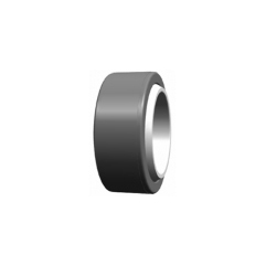
GEZ Steel / PTFE Fabric Series Radial Spherical Plain Bearing dimensions and technical data
İncele
GEZ Steel / PTFE Fabric Series Radial Spherical Plain Bearing dimensions and technical data
İncele
GEG Steel / PTFE Fabric Series Radial Spherical Plain Bearing dimensions and technical data
İncele
GE Steel / PTFE Fabric Series Radial Spherical Plain Bearing dimensions and technical data
İncele
GEC Steel / PTFE Composite Series Radial Spherical Plain Bearing dimensions and technical data
İncele
GEH Steel / PTFE Composite Series Radial Spherical Plain Bearing dimensions and technical data
İncele
GEF Steel / PTFE Fabric Series Radial Spherical Plain Bearing dimensions and technical data
İncele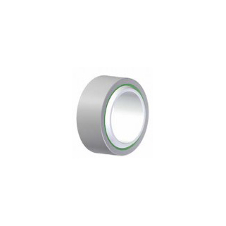
GE Stainless Steel / PTFE Plastic Series Radial Spherical Plain Bearing dimensions and technical data
İncele
GEBK Bronze Series Radial Spherical Plain Bearing dimensions and technical data
İncele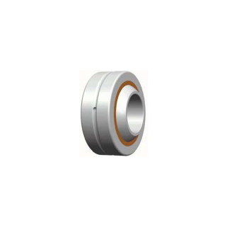
GEBK Bronze Series Radial Spherical Plain Bearing dimensions and technical data
İncele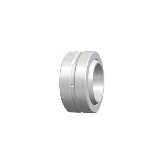

GEGZES GEGZES-2RS Series Radial Spherical Plain Bearing dimensions and technical data
İncele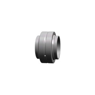
GEZES GEZES-2RS Series Radial Spherical Plain Bearing dimensions and technical data
İncele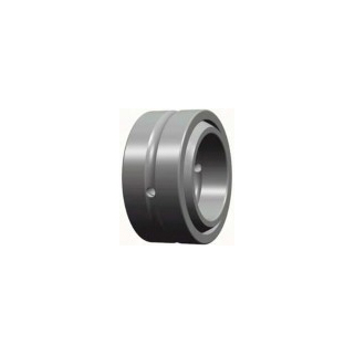
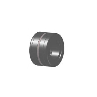
Sliding contact surfaces, Steel / Steel material, dimensions and technical data
İncele
![]()
Welcome to LRS mechanic world!
© LRS Linear Rolling Systems All rights reserved