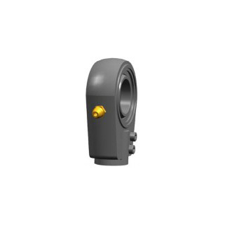
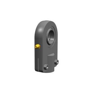
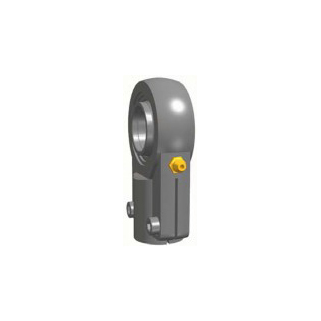
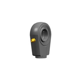
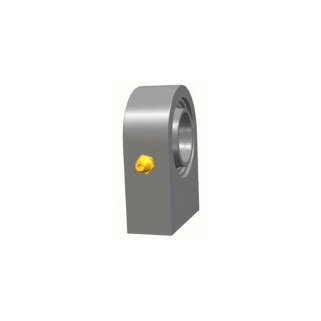
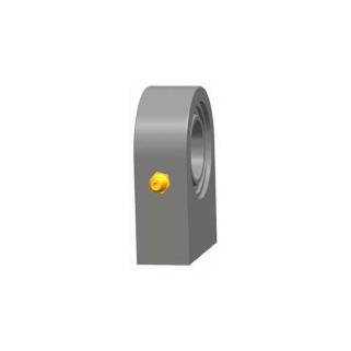
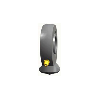
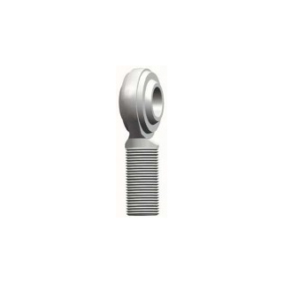
SIA Steel / Steel Series
SIA Steel / Steel Series rod end dimensions and technical data
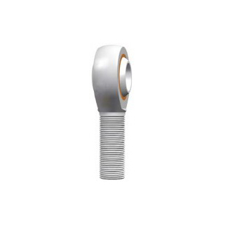
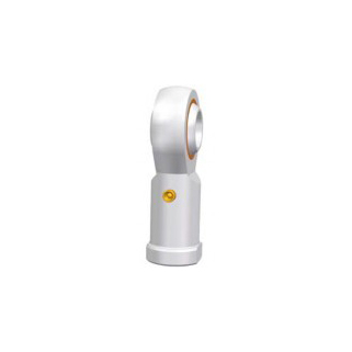
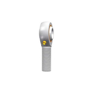
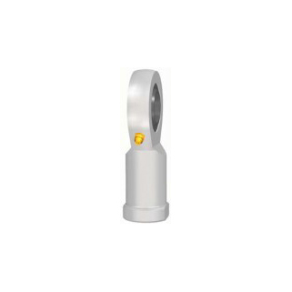
İnceleRod ends consist of an eye-shaped head with integral shank forming a housing and a standard spherical plain bearing, or a spherical plain bearing inner ring, or a spherical plain bearing inner ring and a sliding layer between the bore of the head and the inner ring. As a rule, rod ends are available with left or right-hand female or male threads. LS rod ends have the sliding contact surface combinations steel-on-steel, steel-on-bronze, steel-on-PTFE composite material, steel-on-PTFE fabric and steel-on-PTFE plastic.
LS steel-on-steel and steel-on-bronze rod ends have very wear-resistant sliding surfaces and perform well under conditions of lubricant starvation. Rod ends with this sliding contact surface combination require regular relubrication. They are particularly suited for bearing arrangements where heavy alternating loads have to be accommodated.
LS maintenance-free rod ends sliding contact surfaces have three groups: steel-on-PTFE composite material, steel-on-PTFE fabric and steel-on-PTFE plastic. They have very low friction and can be operated without maintenance. They are used for applications where long bearing lives are required without maintenance, or where operating conditions, such as inadequate lubrication or the absence of lubrication make the use of steel-on-steel bearing inadvisable. The maintenance-free bearings are primarily intended for applications where loads are heavy and have a constant direction.
Inner ring
The ∆dmp and ∆Bs of SI…E, SI…ES, SA…E, SA…ES, SIR…ES, SIRN…ES, SIA…ES, SIQ…ES, SK…ES, SF…ES, SI…C, SA…C, SI…ET-2RS, SA…ET-2RS are the same as radial spherical plain bearings GE…E, GE…ES, GE…C and GE…ET-2RS.
The ∆dmp and ∆Bs of SIGEW…ES, SFEW…ES are the same as radial spherical plain bearings GEEW…ES.
The Δdmp and ΔBs of SIBP…S,SABP…S,SIZP…S, SAZP…S,SIZJ… and SAZJ… are the same as radial spherical plain bearings GEBK…S.
Series SIJK…C, SAJK…C, SIK…C, SAK…C
| d mm | ∆dmp um | ∆Bs um | |||
| over | incl. | max. | min. | max. | min. |
| - | 6 | +12 | 0 | 0 | -150 |
| 6 | 10 | +15 | 0 | 0 | -150 |
| 10 | 12 | +18 | 0 | 0 | -150 |
| 12 | 18 | +18 | 0 | 0 | -200 |
| 18 | 30 | +21 | 0 | 0 | -200 |
Center height deviation
| d mm | ∆hs mm | ∆h1s mm | |||
| over | incl. | max. | min. | max. | min. |
| - | 6 | +0.80 | -1.20 | +0.65 | -1.05 |
| 6 | 20 | +0.80 | -1.20 | +0.80 | -1.20 |
| 20 | 30 | +1.00 | -1.70 | +1.00 | -1.70 |
| 30 | 45 | +1.40 | -2.10 | +1.40 | -2.10 |
| 45 | 60 | +1.80 | -2.70 | +1.80 | -2.70 |
| 60 | 80 | +2.25 | -3.40 | +2.25 | -3.40 |
| 80 | 125 | +2.70 | -3.40 | +2.70 | -3.40 |
| 125 | 200 | +3.20 | -4.20 | +3.20 | -4.20 |
Details of dimension and tolerance symbols see page 25.
Series SI…E, SI…ES,SA…E,SA…ES, SK…ES, SF…ES, SFEW…ES, SIRN…ES, SIR…ES, SIGEW…ES, SIQ…ES, SIA…ES
| d mm | Group normal um | ||
| over | incl. | min. | max. |
| - | 12 | 23 | 68 |
| 12 | 20 | 30 | 82 |
| 20 | 35 | 37 | 100 |
| 35 | 60 | 43 | 120 |
| 60 | 90 | 55 | 142 |
| 90 | 125 | 65 | 165 |
| 125 | 200 | 65 | 192 |
Series SI…C, SA…C, SI…ET-2RS, SA…ET-2RS, SIBP…N, SABP…N, SIZP…N, SAZP…N
| d mm |
Group normal um |
|||
| over | incl. | min. | max. |
|
| - | 12 | 0 | 32 |
|
| 12 | 20 | 0 | 40 |
|
| 20 | 35 | 0 | 50 |
|
| 35 | 60 | 0 | 60 |
|
| 60 | 80 | 0 | 72 |
|
Series SIJ…, SAJ…, SIZJ…, SAZJ…
| d mm | Group normal um | ||
| over | incl. | min. | max. |
| - | 8 | 10 | 30 |
| 8 | 14 | 15 | 60 |
| 14 | 22 | 40 | 80 |
Series SIJK…C, SAJK…C, SIK…C, SAK…C
| d mm | Group normal um | ||
| over | incl. | min. | max. |
| - | 12 | 0 | 32 |
| 12 | 20 | 0 | 40 |
| 20 | 30 | 0 | 50 |
Series SIBP…S, SABP…S, SIZP…S, SAZP…S
| d mm | Group normal | ||
| over | incl. | min. | max. |
| - | 30 | 0 | 35 |
Shaft fits
| Operating conditions | Tolerance |
| With indeterminate loads | n6, p6 |
| Normal conditions | h6, h7 |
Thread
| Male thread | Female thread |
| 6g | 6H |
| UNF-2A | UNF-2B |
Shaft diameter tolerances
|
Shaft diameter mm |
Shaft diameter tolerances um |
|||||||||
| h6 | h7 | n6 | p6 | |||||||
| over | incl. | high | low | high | low | high | low | high | low | |
| 3 | 6 | 0 | -8 | 0 | -12 | +16 | +8 | +20 | +12 | |
| 6 | 10 | 0 | -9 | 0 | -15 | +19 | +10 | +24 | +15 | |
| 10 | 18 | 0 | -11 | 0 | -18 | +23 | +12 | +29 | +18 | |
| 18 | 30 | 0 | -13 | 0 | -21 | +28 | +15 | +35 | +22 | |
| 30 | 50 | 0 | -16 | 0 | -25 | +33 | +17 | +42 | +26 | |
| 50 | 80 | 0 | -19 | 0 | -30 | +39 | +20 | +51 | +32 | |
| 80 | 120 | 0 | -22 | 0 | -35 | +45 | +23 | +59 | +37 | |
| 120 | 180 | 0 | -25 | 0 | -40 | +52 | +27 | +68 | +43 | |
| 180 | 200 | 0 | -29 | 0 | -46 | +60 | +31 | +79 | +50 | |
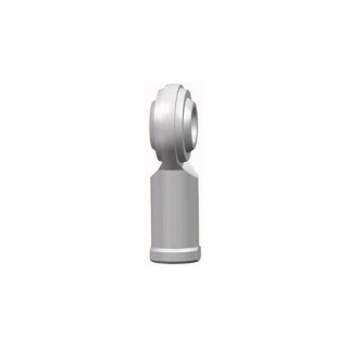
SAZP Steel / PTFE Pastic Series rod end dimensions and technical data
İncele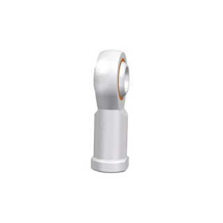
SIZP Steel / PTFE Pastic Series rod end dimensions and technical data
İncele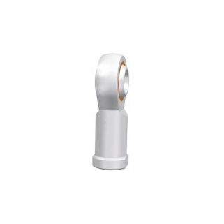
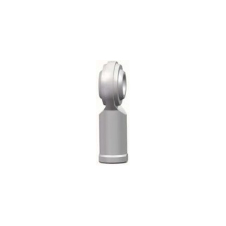
SAB-SIB Steel / PTFE Pastic Series rod end dimensions and technical data
İncele
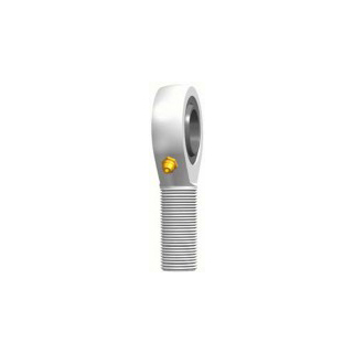
SAK-SIK Steel / PTFE Composite Series rod end dimensions and technical data
İncele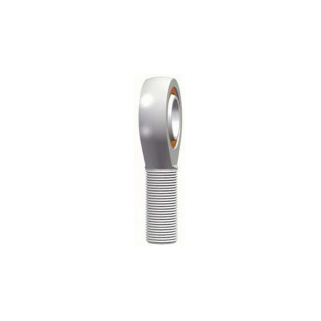
SAJK Steel / PTFE Composite Series rod end dimensions and technical data
İncele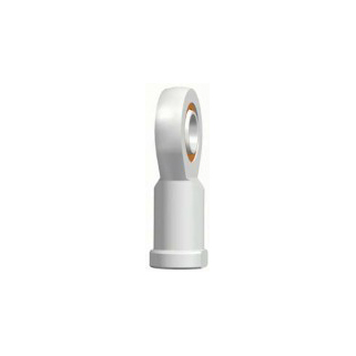
SIJK Steel / PTFE Composite Series rod end dimensions and technical data
İncele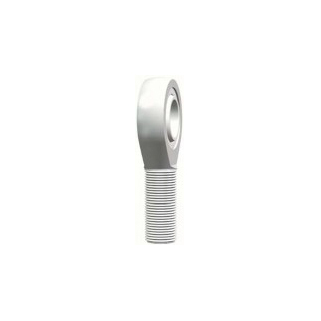
SA Steel / PTFE Composite - Fabric Series rod end dimensions and technical data
İncele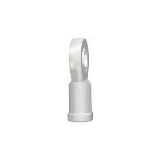
SI Steel / PTFE Composite - Fabric Series rod end dimensions and technical data
İncele

![]()
Welcome to LRS mechanic world!
© LRS Linear Rolling Systems All rights reserved