GAC Steel / PTFE Plastic Series
GAC Steel / PTFE Fabric Series angular contact spherical plain bearing dimensions and technical data
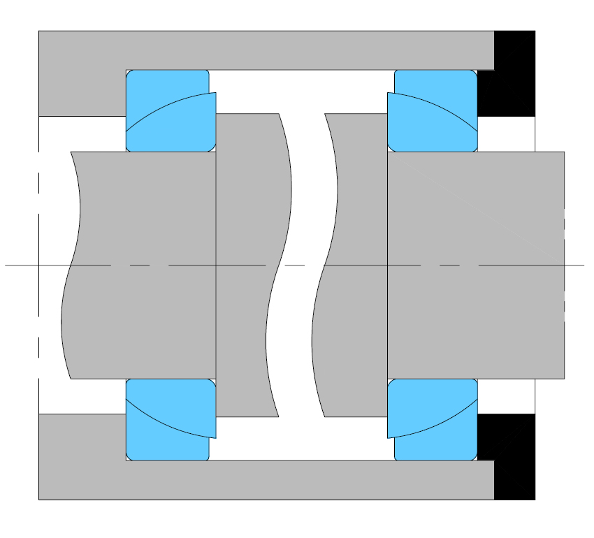
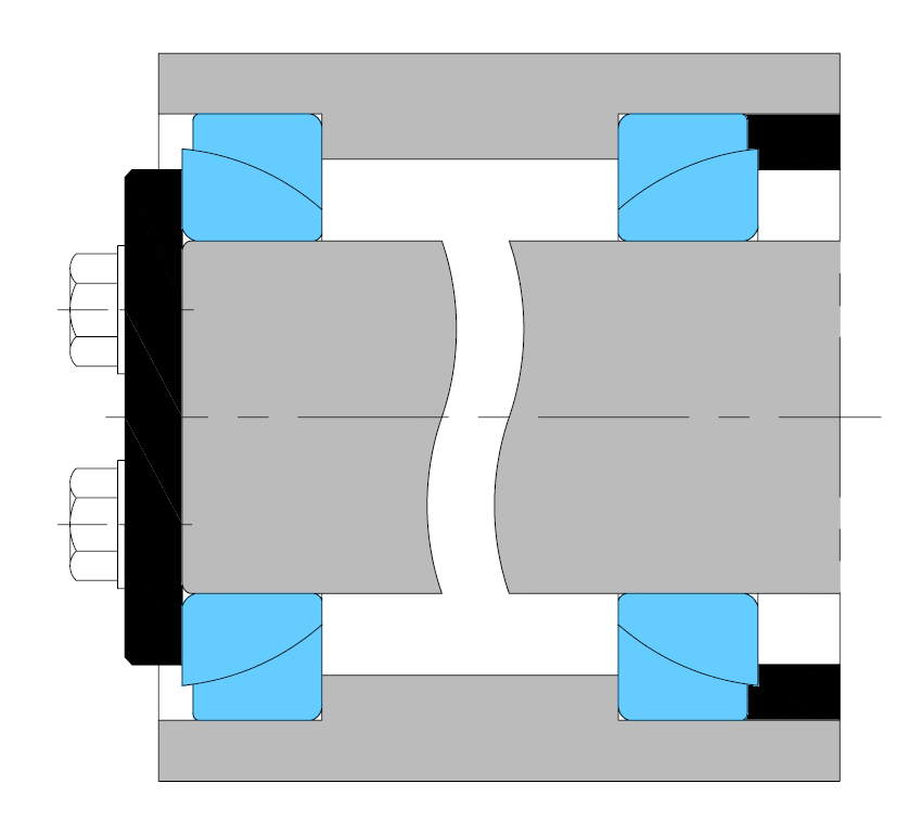
İnceleThe sphered sliding contact surfaces of angular contact spherical plain bearings are inclined at an angle to the bearing axis. They are therefore particularly suitable for carrying combined (radial and axial) loads. A single angular contact spherical plain bearing can only accept axial loads acting in one direction. Under radial loads, a force acting in the axial direction is produced in the bearing which must always be opposed by an equal force acting in the opposite direction.
Therefore, the bearings are usually adjusted against a second bearing. When two angular contact spherical plain bearings are arranged so that their sphere centres coincide, a clearance-free radial spherical plain bearing is obtained which can accommodate heavy radial loads as well as heavy axial loads in both directions. LS angular contact spherical plain bearings are available with different sliding contact surface combinations, i.e. the sliding surfaces of inner and outer rings are made from different materials. There are two main groups: steel-on-steel angular contact spherical plain bearings and maintenance-free angular contact spherical plain bearings.
LS steel-on-steel angular contact spherical plain bearings are made of carbon chromium steel and are hardened and phosphated, it has characteristics of wear-resistance and wear-corrosion. The inner and outer rings sliding contact surface are treated with molybdenum disulphide. Bearings with this sliding contact surface combination require regular relubrication. To facilitate efficient lubrication, outer ring has an annular groove and two lubrication holes. The high strength of the sliding surfaces makes these bearings especially suitable for bearing arrangements where heavy loads of alternating direction, shock loads or heavy static loads have to be accommodated.
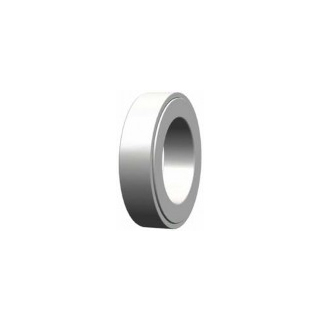
LS maintenance-free angular contact spherical plain bearings have sliding contact surface combinations steel-on-PTFE fabric and steel-on-PTFE plastic, they have very low friction and can be operated without maintenance, any lubrication of the sliding contact surfaces will shorten bearing life. They are used for applications where long bearing lives are required without maintenance, or where operating conditions, such as inadequate lubrication or the absence of lubrication make the use of steel-on-steel bearing inadvisable. The maintenance-free bearings are primarily intended for applications where loads are heavy and have a constant direction.
Tolerances for angular contact spherical plain bearings
Inner ring and width of bearing
| d mm | ∆dmp um | Vdp um | Vdm um | ∆Bs um | ∆Ts um | ||||
| over | incl. | max. | min. | max. | max. | max. | min. | max. | min. |
| - | 50 | 0 | -12 | 12 | 9 | 0 | -240 | +250 | -400 |
| 50 | 80 | 0 | -15 | 15 | 11 | 0 | -300 | +250 | -500 |
| 80 | 120 | 0 | -20 | 20 | 15 | 0 | -400 | +250 | -600 |
| 120 | 180 | 0 | -25 | 25 | 19 | 0 | -500 | +350 | -700 |
| 180 | 200 | 0 | -30 | 30 | 23 | 0 | -600 | +350 | -800 |
Outer ring
| D mm | ∆Dmp um | VDp um | VDmp um | ∆Cs um | |||
| over | incl. | max. | min. | max. | max. | max. | min. |
| - | 50 | 0 | -14 | 14 | 11 | 0 | -240 |
| 50 | 80 | 0 | -16 | 16 | 12 | 0 | -300 |
| 80 | 120 | 0 | -18 | 18 | 14 | 0 | -400 |
| 120 | 150 | 0 | -20 | 20 | 15 | 0 | -500 |
| 150 | 180 | 0 | -25 | 25 | 19 | 0 | -500 |
| 180 | 250 | 0 | -30 | 30 | 23 | 0 | -600 |
| 250 | 315 | 0 | -35 | 35 | 26 | 0 | -700 |
Details of dimension and tolerance symbols see page 25
Fits of angular contact spherical plain bearings
Shaft fits
| Operating conditions | Sliding contact surface combination | ||
| requiring maintenance | maintenance-free | ||
| Loads of all kinds,interference fit | m6 | m7 | |
Housing fits
| Operating conditions | Sliding contact surface combination | ||
| requiring maintenance | maintenance-free | ||
| Loads of all kinds,interference fit | M7 | M7 | |
| Loads of all kinds,can generally be displaced axially | J7 | J7 | |
Shaft diameter tolerances
| Shaft diameter mm | Shaft diameter tolerances um | ||
| m6 | |||
| over | incl. | high | low |
| - | 30 | +21 | +8 |
| 30 | 50 | +25 | +9 |
| 50 | 80 | +30 | +11 |
| 80 | 120 | +35 | +13 |
| 120 | 180 | +40 | +15 |
| 180 | 250 | +46 | +17 |
Housing bore tolerances
| Housing bore diameter mm | Housing bore tolerances um | |||||
| J7 | M7 | |||||
| over | incl. | low | high | low | high | |
| - | 50 | -11 | +14 | -25 | 0 | |
| 50 | 80 | -12 | +18 | -30 | 0 | |
| 80 | 120 | -13 | +22 | -35 | 0 | |
| 120 | 150 | -14 | +26 | -40 | 0 | |
| 150 | 180 | -14 | +26 | -40 | 0 | |
| 180 | 250 | -16 | +30 | -46 | 0 | |
| 250 | 315 | -16 | +36 | -52 | 0 | |
GAC Steel / PTFE Fabric Series angular contact spherical plain bearing dimensions and technical data
İncele
GAC Steel / PTFE Fabric Series angular contact spherical plain bearing dimensions and technical data
İncele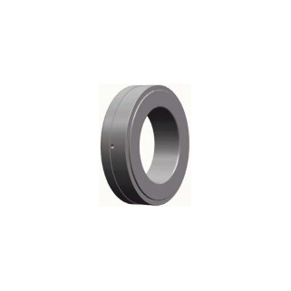
GAC Steel / Steel Series angular contact spherical plain bearing dimensions and technical data
İncele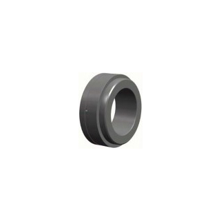
GACZ Steel / Steel Series angular contact spherical plain bearing dimensions and technical data
İncele
![]()
Welcome to LRS mechanic world!
© LRS Linear Rolling Systems All rights reserved